
TIPS & TRICKS
TIPS & TRICKS
1) RabbitMQ FQDN configuration in vRA 7.3
In vRA 7.3 before configuring the appliance the RabbitMQ configuration needs to be updated to use a FQDN (Fully Qualified Domain Name). This is something new that has been introduced in vRA 7.3.
The correct procedure for configuring this is listed below:
1. Log in as root to a console session on the vRealize Automation appliance.
2. Stop the RabbitMQ service.
service rabbitmq-server stop
3. Stop rabbitmq monitor:
service cluster-rabbitmq-monitor stop
4. Open the following file in a text editor.
/etc/rabbitmq/rabbitmq-env.conf
5. Set the following property to true.
USE_LONGNAME=true
6. Save and close the rabbitmq-env.conf file.
7. Reset RabbitMQ.
vcac-vami rabbitmq-cluster-config reset-rabbitmq-node
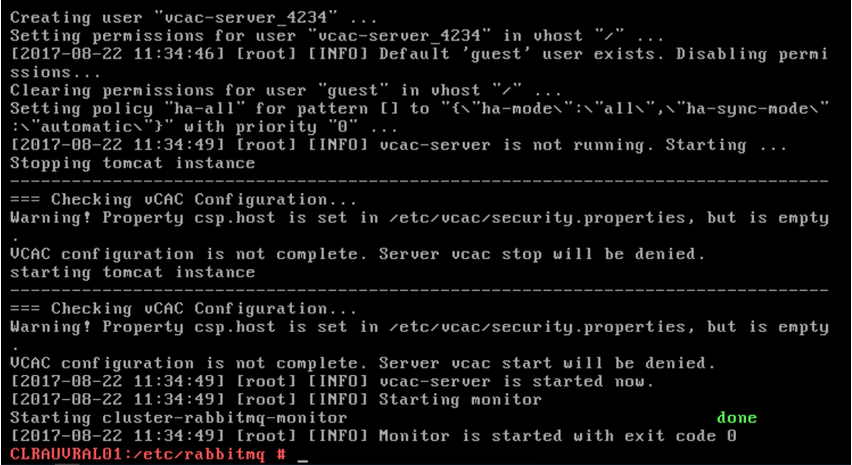
8. Verify that the RabbitMQ service is started.
vcac-vami rabbitmq-cluster-config get-rabbitmq-status
If executed correctly the following will be the output:
2) How to install a Second Web Server in vRA 7.3 in a distributed configuration if the installation fails using the Standard installer (not the installation wizard):
If you try and install a second web server using the standard installer you will most likely get the following certificate error:
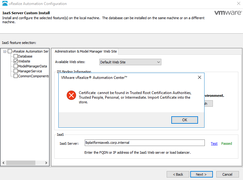
Don't worry, the way around this is to use one of the cool features introduced in vRA 7.1 which is the REST API based component installation/configuration feature.
Pre-reqs for this are as follows:
a) vRA appliance deployed and configured.
b) Windows Server 2008/R2, 2012/R2 or 2016 for the 2nd Web Server with all the Pre-reqs installed.
c) vRA Management Agent installed on the Windows Server to be used.
d) vRA IaaS Service account needs to have administrator priviledges on the Windows Server that is to be used.
Follow the steps below to get the Second Web Server installed:
a) To access the configuration page connect to the vRA Appliance VAMI interface i.e. https://<vra appliance>:5480/config
This will bring up the page shown below:
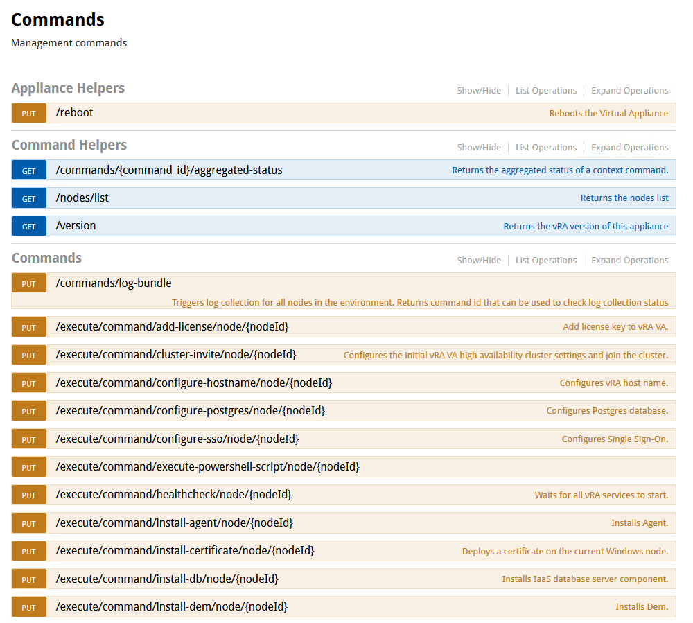
b) Next we need to get the NodeId
of the management agent running on the new Windows Server. To do this execute the GET /nodes/list
command as shown in the screenshot below:
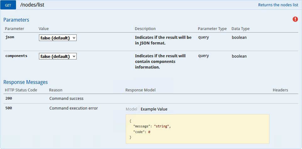
Click on the Red Exclamation mark
and enter the root credentials of the vRA appliance.
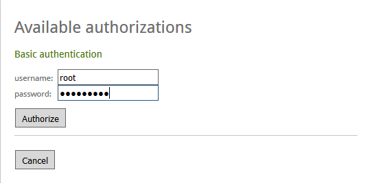
Change the json
and components
values to true and select the Authorize
button.
Then Select the Try it out!
button. This should give us the NodeId we need for the Management Agent running on the Windows Server as per the screenshot below:

c) Now that we have the NodeId we can now run the PUT /execute/command/install-web/node/{nodeid}
command as shown in the screenshot below:
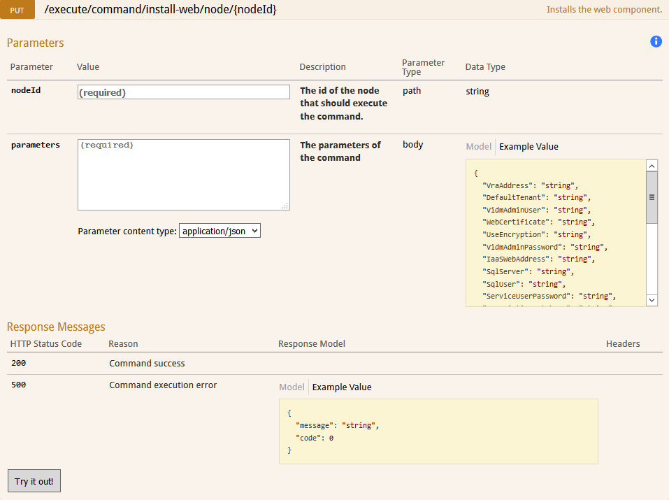
d) To install the Second Web Server I used the following:
nodeId:
F435B93F-1949-44AC-B9F0-05D058804D30
parameters:
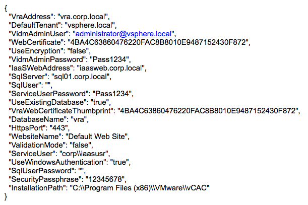
Note:
If you have a backslash (\) in the parameters then add one more backslash after it i.e. \\
e) Once you have your parameters ready, copy them into the parameters section, ensure the ValidationMode
is set to True
and Select the Try it Out!
button.
Note:
If you get the following error 10008
in the response body, then this can be ignored:
If the response comes back with a status of 200
or you get the error 10008
above with a status of 500, then change the ValidationMode
to False
and Select the Try it Out!
button.
This will start the 2nd Web Server installation. Once this completes you should get a response status of 200.
This means the Second web server has been installed.
That's it !
3) vRealize Orchestrator REST API
vRealize Orchestrator has a REST API that provides functionality to allow communication with the Orchestrator server directly through HTTP and perform various workflow-related operations over workflows.
The Orchestrator REST API exposes the objects from the inventories of the Orchestrator server and the installed plug-ins as resources at predefined URLs. HTTP calls are made at these URLs to trigger operations in Orchestrator. In this way, various tasks can be performed over workflows, such as:
- Run a workflow, schedule a workflow, retrieve the runs of a workflow, answer to a user
interaction, and cancel a workflow run.
- Retrieve details about a workflow such as its input and output parameters and its
presentation.
- Retrieve details about a workflow run, such as its state, generated logs, start date, and
end date.
- Browse the inventories of Orchestrator and the installed plug-ins.
- Import and export workflows, actions, and packages.
GET and POST REST API Parameters
GET:
To GET a REST request to retrieve information about a workflow the following parameters are required:
POST:
To POST a REST request to initiate a vRealize Orchestrator Workflow the following parameters are required:
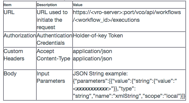
Note:
If the parameters are all correct in the POST request then the status of 202 Accepted
will be returned.
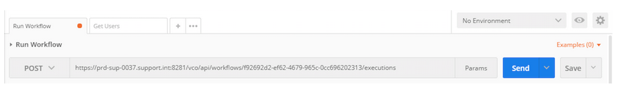
Example REST Call using Postman Extension in Chrome
The following screenshots show the POST REST call parameters using Postman’s API Development Environment (ADE) extension in Chrome to execute a vRealize Orchestrator workflow:
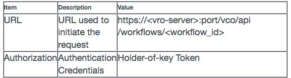
a) URL:
This is the API URL that is to be used to invoke the vRO workflow. Screenshot below shows the URL to execute a workflow:
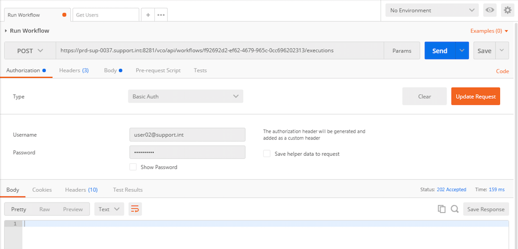
b) Authorization:
These are the Credentials (Username and Password) used to invoke the REST call. When saved this creates the Holder-of-key token that will be used in the POST REST call.
c) Headers:
These are the Custom Headers that are required in order to make the POST REST call. Screenshot below shows the Accept and Content-Type headers that need to be defined for VRO Workflow execution.
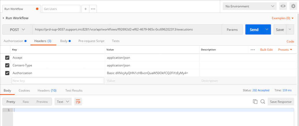
Note:
The Authorization header gets added automatically once the credentials have been entered and saved on the Authorization tab.
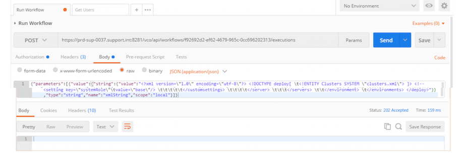
d) Body:
The Body contains the input parameters for the workflow. The Screenshot below shows an example of the list of parameters that can be passed to invoke a vRO workflow:
In vRA 7.4 if you have a Directory created using Active Directory Integrated Windows Authentication (IWA) which has one domain selected as shown below:
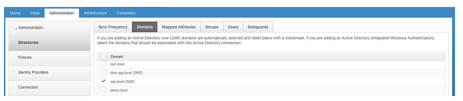
And when you try to add a second domain as shown below:
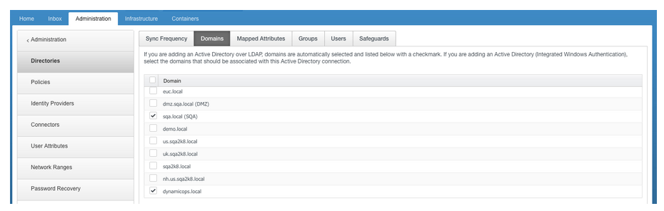
Then you get the error “Could not resolve domains” as listed below:

To fix this issue, SSH onto the master VRA appliance as root and do the following:
a) Navigate to /etc
folder.
b) VI the krb5.conf
file.
c) Add the additional domain information under the [realms]
section as follows:
[realms]
DOMAIN1.LOCAL = {
auth_to_local = RULE:[1:$0\$1](^domain1\.LOCAL\\.*)s/^domain1\.LOCAL/domain1/
auth_to_local = RULE:[1:$0\$1](^domain1\.LOCAL\\.*)s/^domain1\.LOCAL/domain1/
auth_to_local = RULE:[1:$0\$1](^domain3\.NET\\.*)s/^domain3\.NET/domain3/
auth_to_local = RULE:[1:$0\$1](^domain2\.DOMROOT\.INTERNAL\\.*)s/^domain2\.DOMROOT\.INTERNAL/domain2/
auth_to_local = DEFAULT
kdc = kdc1.domain1.local
kdc = kdc2.domain1.local
}
DOMAIN2.LOCAL = {
kdc = kdc1.domain2.local
kdc = kdc2.domain2.local
}
Example:
[realms]
SQA.LOCAL = {
auth_to_local = RULE:[1:$0\$1](^SQA\.LOCAL\\.*)s/^SQA\.LOCAL/SQA/
auth_to_local = RULE:[1:$0\$1](^SQA\.LOCAL\\.*)s/^SQA\.LOCAL/SQA/
auth_to_local = RULE:[1:$0\$1](^DEMO\.LOCAL\\.*)s/^DEMO\.LOCAL/DEMO/
auth_to_local = RULE:[1:$0\$1](^EUC\.LOCAL\\.*)s/^EUC\.LOCAL/EUC/
auth_to_local = RULE:[1:$0\$1](^UK\.SQA2K8\.LOCAL\\.*)s/^UK\.SQA2K8\.LOCAL/UK/
auth_to_local = RULE:[1:$0\$1](^US\.SQA2K8\.LOCAL\\.*)s/^US\.SQA2K8\.LOCAL/US/
auth_to_local = RULE:[1:$0\$1](^NH\.US\.SQA2K8\.LOCAL\\.*)s/^NH\.US\.SQA2K8\.LOCAL/NH/
auth_to_local = RULE:[1:$0\$1](^SQA2K8\.LOCAL\\.*)s/^SQA2K8\.LOCAL/SQA2K8/
auth_to_local = RULE:[1:$0\$1](^DMZ\.SQA\.LOCAL\\.*)s/^DMZ\.SQA\.LOCAL/DMZ/
auth_to_local = RULE:[1:$0\$1](^DYNAMICOPS\.LOCAL\\.*)s/^DYNAMICOPS\.LOCAL/DYNAMICOPS/
auth_to_local = DEFAULT
kdc = sqa-dc-1.sqa.local
kdc = sqa-dc-2.sqa.local
}
DYNAMICOPS.LOCAL = {
kdc = dc-1.dynamicops.local
kdc = dc-2.dynamicops.local
}
d) Save the file.
e) Ensure the file /etc/krb5.conf
has Permissions set to 644 & Ownership
root:root.
f) Ensure there is no other krb5.conf file in any other directory on the VRA Appliance.
g) Restart the horizon workspace service as follows:
Service horizon-workspace restart
h) If you have multiple appliances then repeat steps a) to g) above for each appliance.
i) Try adding the domain again.
It should work now !
5) Add DNS A and PTR Records into Windows Active Directory
A typical use case would be to add the DNS A and PTR records of a Linux VM into Windows Active Directory as part of the vRealize Automation provisioning process.
In order to achieve this the following are required:
a) vRealize Automation 7.x installed and operational.
b) vRealize Orchestrator 7.x installed and operational (I used the one embedded in vRA).
c) A Windows machine with Powershell installed.
d) The vRO Workflow Add DNS A and PTR Records attached below.
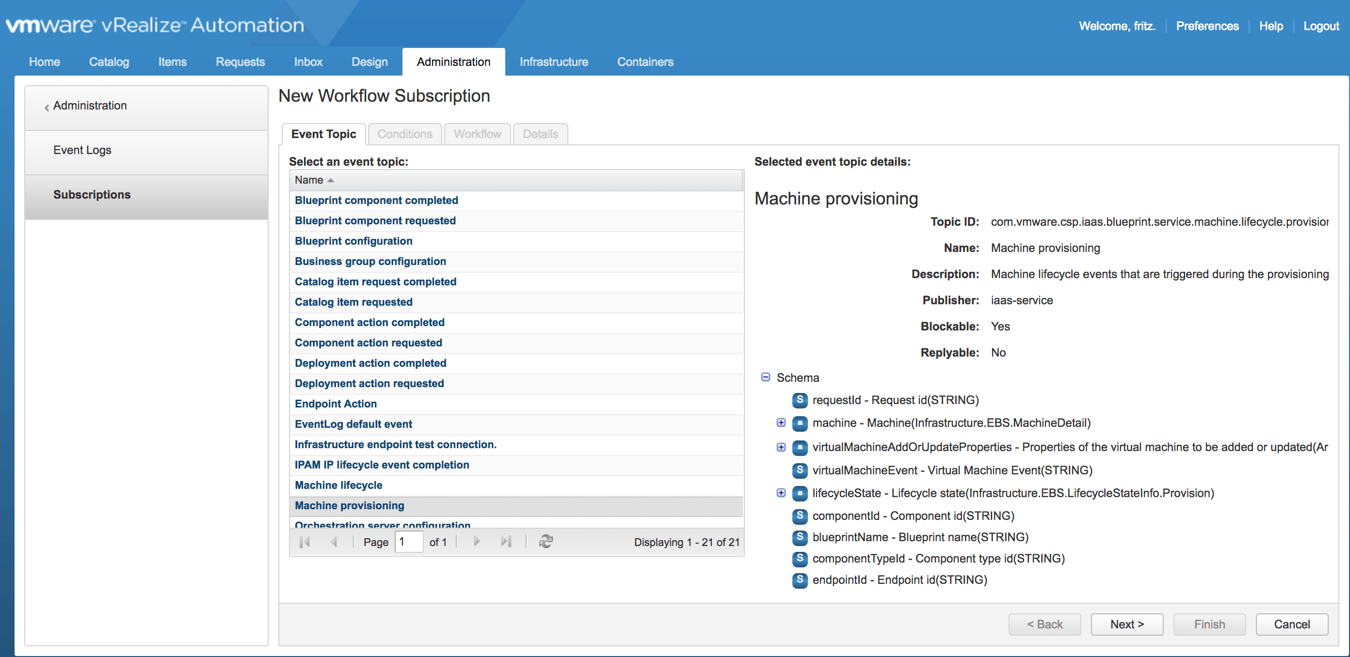
e) In vRA create an Event Subscription to trigger the vRO Workflow above at the MachineProvisioned state.
Procedure:
a) Login into vRO with admin access.
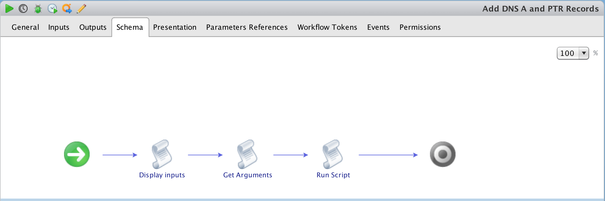
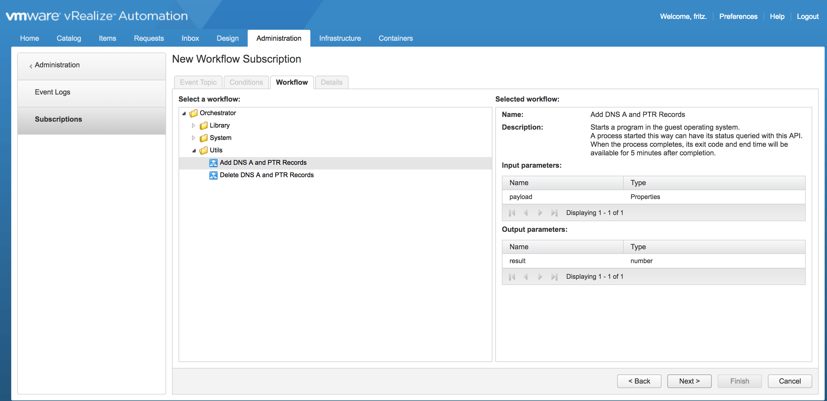
b) Import the attached workflow Add DNS A and PTR Records into vRO.
c) The following workflow will be imported:
A typical use case would be to add the DNS A and PTR records of a Linux VM into Windows Active Directory as part of the vRealize Automation provisioning process.
In order to achieve this the following are required:
a) vRealize Automation 7.x installed and operational.
b) vRealize Orchestrator 7.x installed and operational (I used the one embedded in vRA).
c) A Windows machine with Powershell installed.
d) The vRO Workflow Add DNS A and PTR Records attached below.
e) In vRA create an Event Subscription to trigger the vRO Workflow above at the MachineProvisioned state.
Procedure:
a) Login into vRO with admin access.
b) Import the attached workflow Add DNS A and PTR Records into vRO.
c) The following workflow will be imported:
d) Edit the Workflow and update the following attribute values to the correct ones for your environment:
i) programPath – Path to powershell.exe e.g. C:\Windows\System32\WindowsPowerShell\v1.0\powershell.exe
ii) vmUsername – Username to connect to the powershell host in the format Domain\Username.
iii) vmPassword – Password for the username above.
iv) vCenterVM – This is the powershell host that will be used.
v) dc – Name of Domain Controller to use.
vi) zonename – Name of the Zone that is to be used e.g FQDN of domain.

e) Login into vRA as a Tenant Admin.
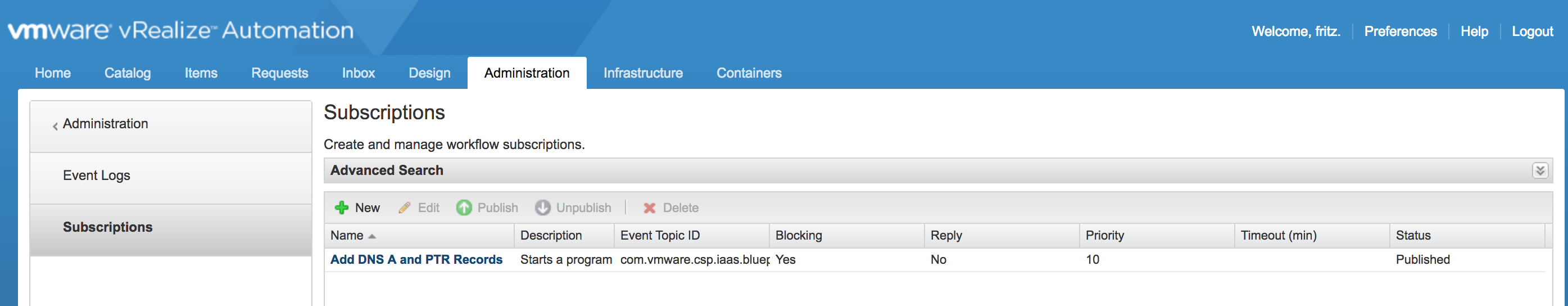
f) Go to Administration – Events – Subscriptions.
f) Go to Administration – Events – Subscriptions.
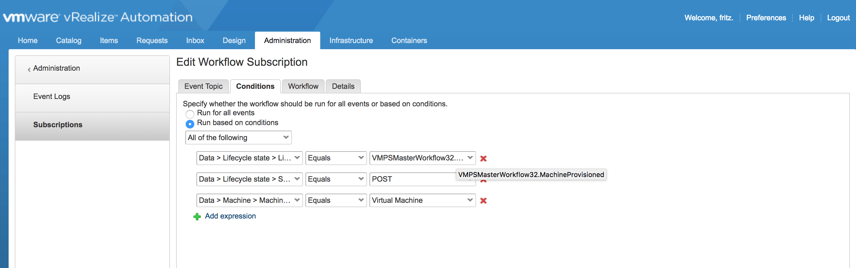
g) Create a Subscription to trigger the vRO Workflow imported in b) above to be executed in the MachineProvisioned
state as shown below:
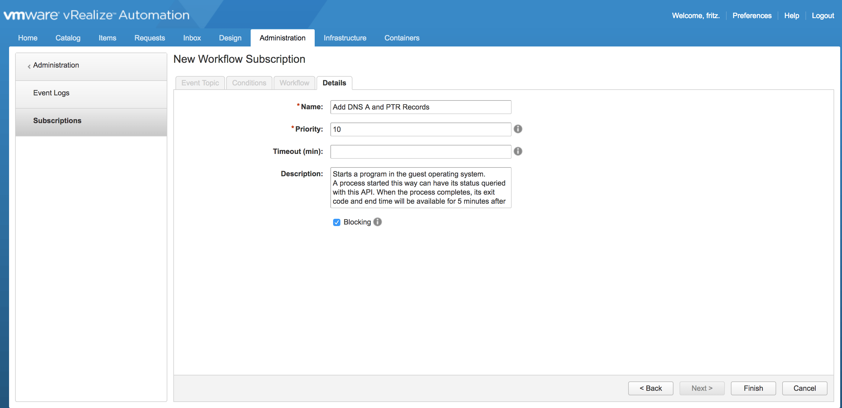
h) Publish the Subscription created in f) above:
i) That’s it !, Provision a VM and check in Active Directory DNS if the A and PTR records have been created for that VM.
vRO Workflow attached below:
vRO Workflow attached below:
Add DNS A and PTR Records workflow.zip
ii) vmUsername – Username to connect to the powershell host in the format Domain\Username.
iii) vmPassword – Password for the username above.
iv) vCenterVM – This is the powershell host that will be used.
v) dc – Name of Domain Controller to use.
6) Delete DNS A and PTR Records from Windows Active Directory
A typical use case would be to Delete the DNS A and PTR records of a Linux VM from Windows Active Directory as part of the vRealize Automation decommissioning process.
In order to achieve this the following are required:
a) vRealize Automation 7.x installed and operational.
b) vRealize Orchestrator 7.x installed and operational (I used the one embedded in vRA).
c) A Windows machine with Powershell installed.
d) The vRO Workflow Delete DNS A and PTR Records attached below.
e) In vRA create an Event Subscription to trigger the vRO Workflow above at the Disposing state.
Procedure:
a) Login into vRO with admin access.
b) Import the attached workflow Delete DNS A and PTR Records into vRO.
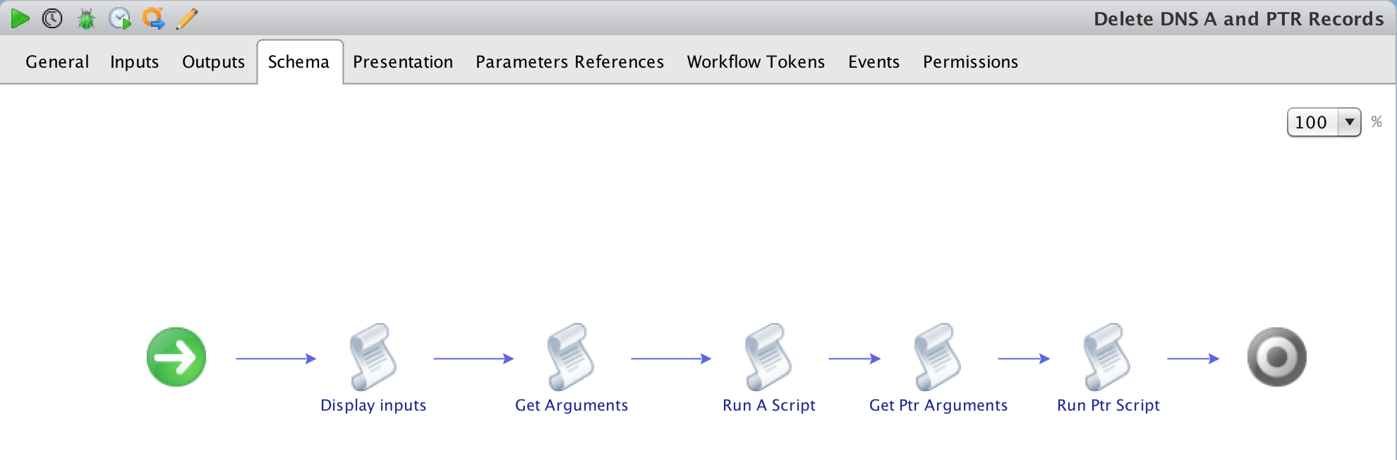
c) The following workflow will be imported:
A typical use case would be to Delete the DNS A and PTR records of a Linux VM from Windows Active Directory as part of the vRealize Automation decommissioning process.
In order to achieve this the following are required:
a) vRealize Automation 7.x installed and operational.
b) vRealize Orchestrator 7.x installed and operational (I used the one embedded in vRA).
c) A Windows machine with Powershell installed.
d) The vRO Workflow Delete DNS A and PTR Records attached below.
e) In vRA create an Event Subscription to trigger the vRO Workflow above at the Disposing state.
Procedure:
a) Login into vRO with admin access.
b) Import the attached workflow Delete DNS A and PTR Records into vRO.
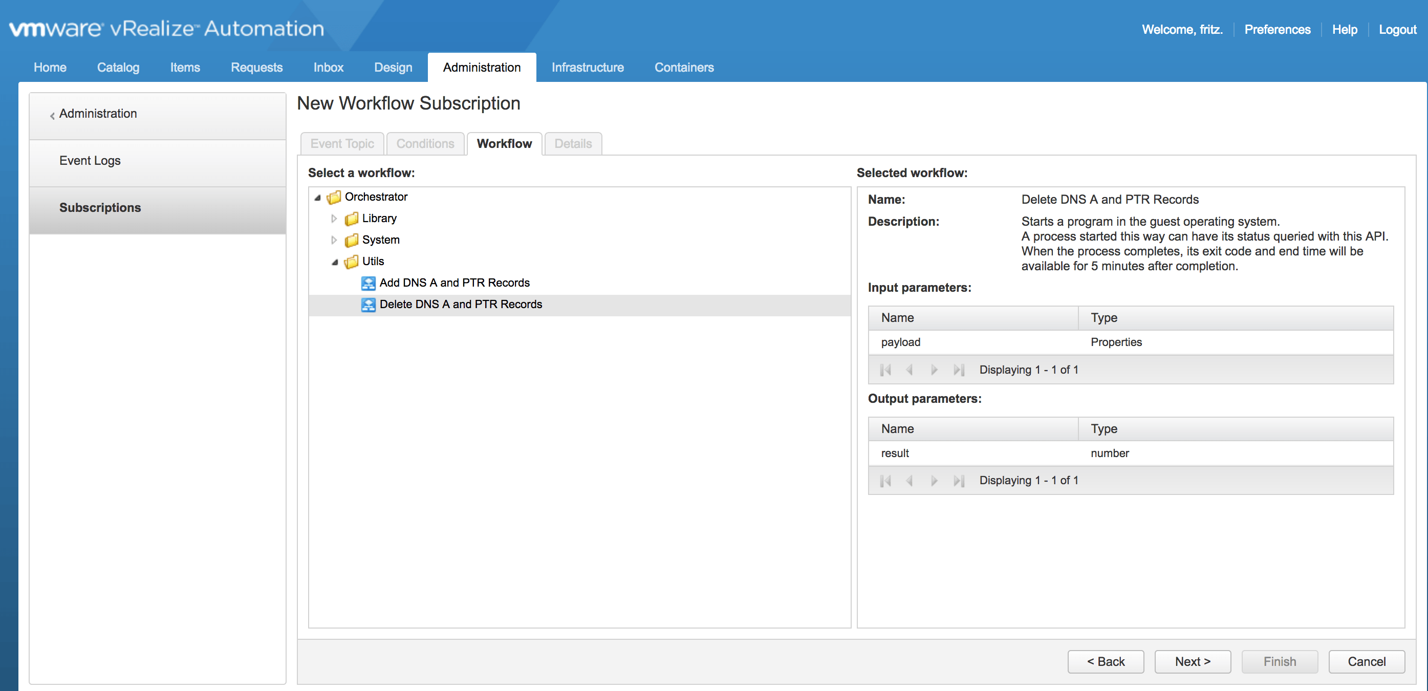
c) The following workflow will be imported:
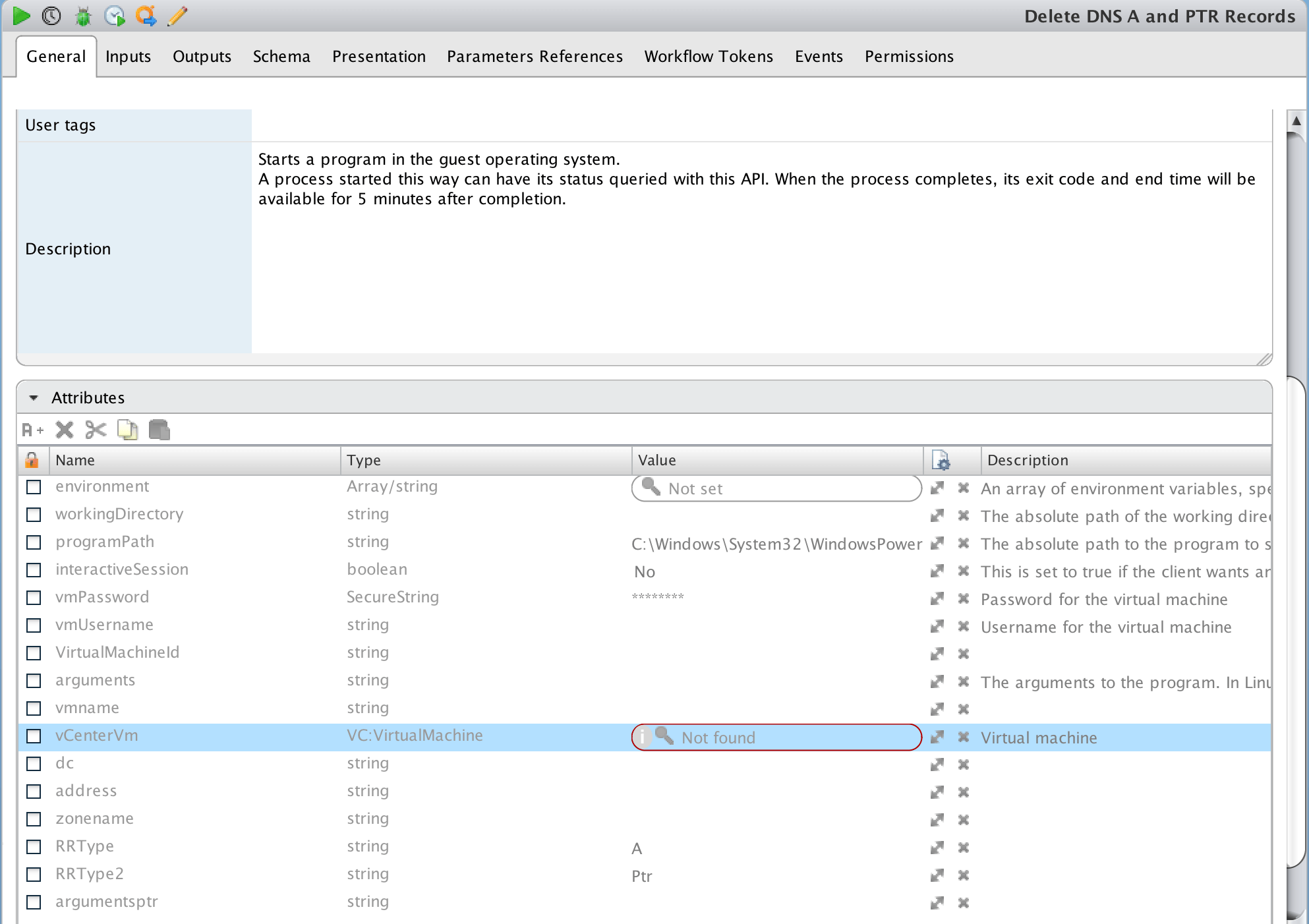
d) Edit the Workflow and update the following attribute values to the correct ones for your environment:
i) programPath – Path to powershell.exe e.g. C:\Windows\System32\WindowsPowerShell\v1.0\powershell.exeii) vmUsername – Username to connect to the powershell host in the format Domain\Username.
iii) vmPassword – Password for the username above.
iv) vCenterVM – This is the powershell host that will be used.
v) dc – Name of Domain Controller to use.
vi) zonename – Name of the Zone that is to be used e.g FQDN of domain.
e) Login into vRA as a Tenant Admin.
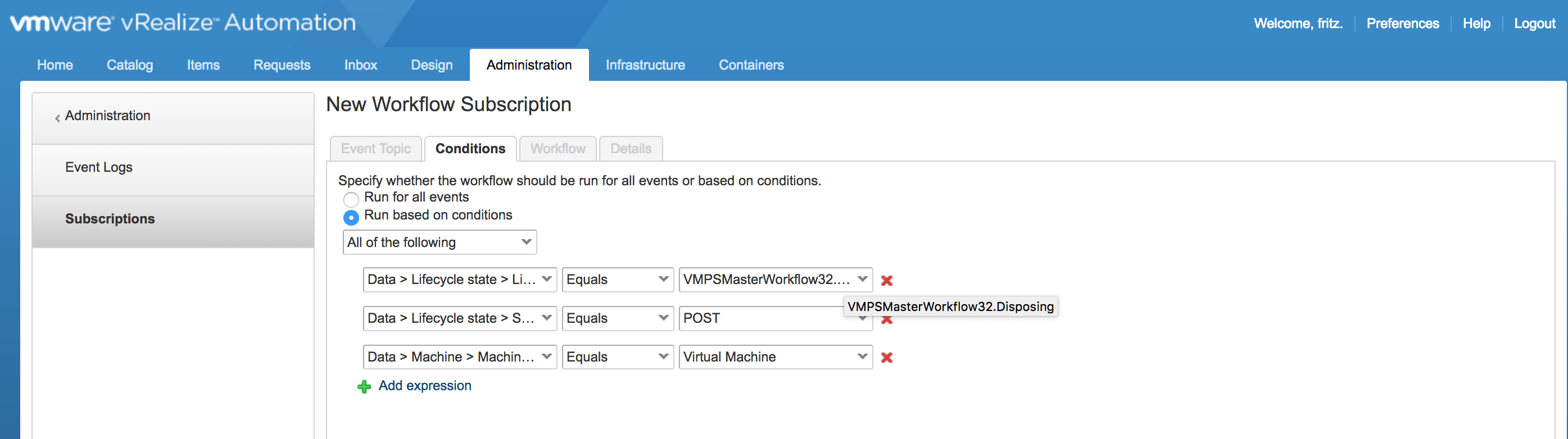
f) Go to Administration – Events – Subscriptions.
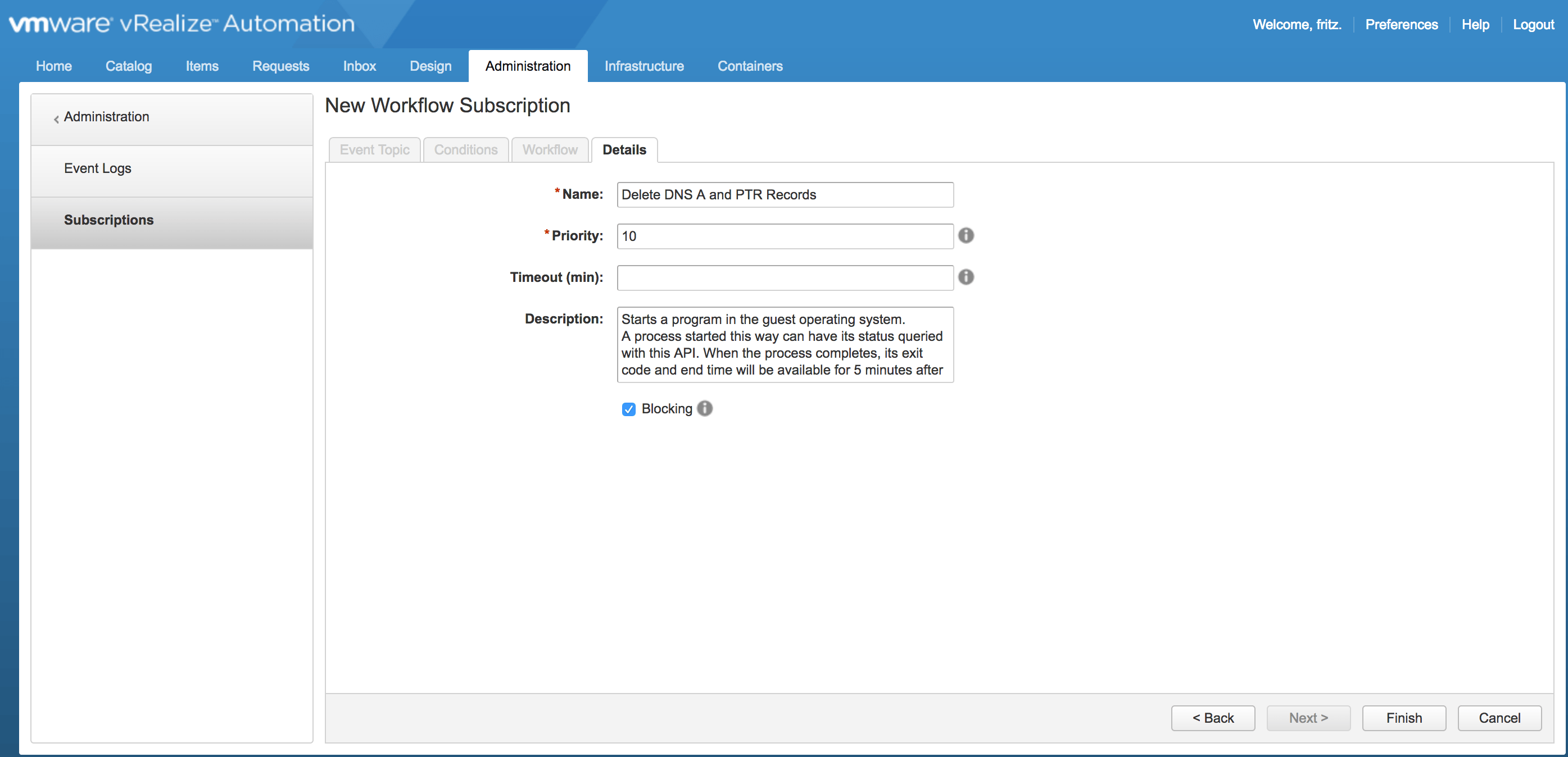
g) Create a Subscription to trigger the vRO Workflow imported in b) above to be executed in the Disposing state as shown below:
f) Go to Administration – Events – Subscriptions.
g) Create a Subscription to trigger the vRO Workflow imported in b) above to be executed in the Disposing state as shown below:
h) Publish the Subscription created in f) above:
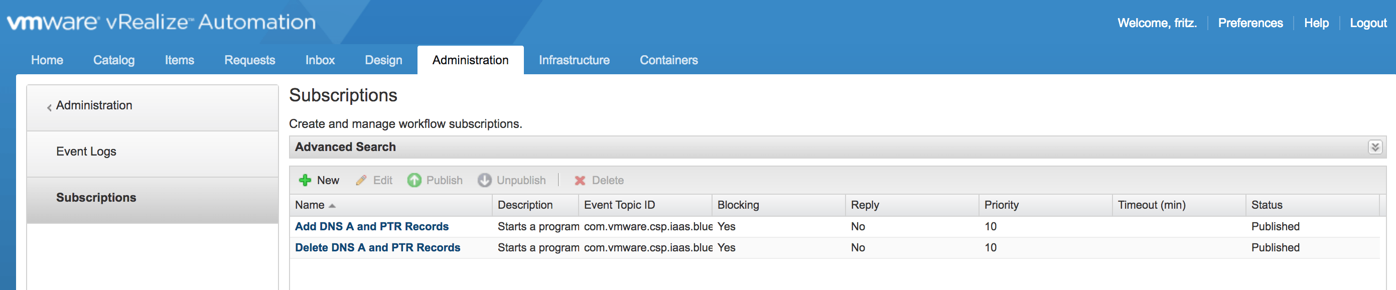
i) That’s it !, Destroy a VM and check in Active Directory DNS if the A and PTR records have been deleted for that VM.
vRO Workflow attached below:
Delete DNS A and PTR Records workflow.zip
vRO Workflow attached below:
7) VRA 7.5 – Adding/Updating the vRA License key using the API
To add or update the vRA License key using the API, follow the process below:
a) Connect to the following URL:
https://<FQDN_of_vRA_Appliance>:5480/config
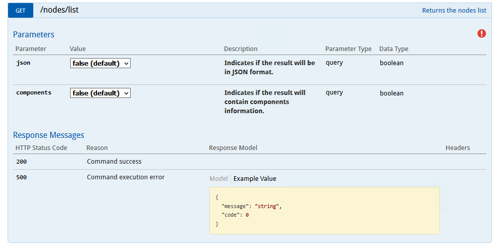
b) Click on the GET /nodes/list
command. The following will be displayed:
c) Click on the red
exclamation mark and enter the root credentials in the screenshot below:
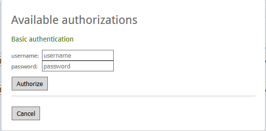
d) Once done, Click on Authorize.
e) Once the credentials are entered and validated the exclamation mark will turn blue
as shown below:
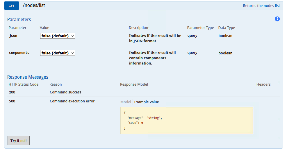
f) Click on Try it out!
button.
g) The node information will be listed in the Response body section as shown in the example below:
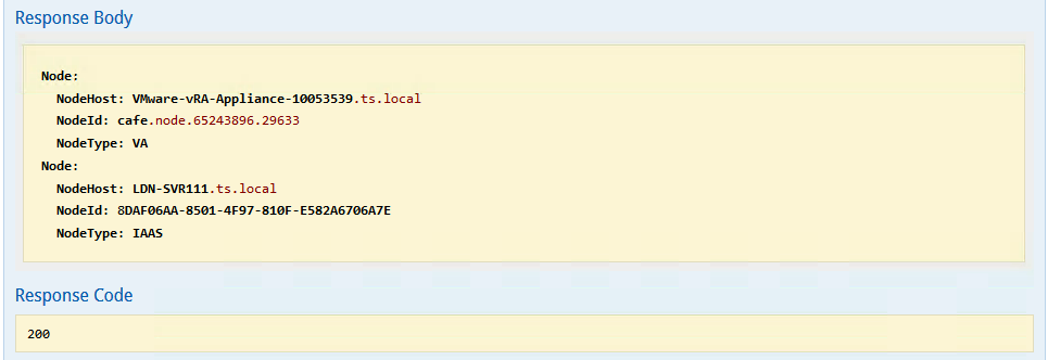
h) Make a note of the NodeId
e.g. cafe.node.65243896.29633
of NodeType: VA, this will be used when adding/updating the license key.
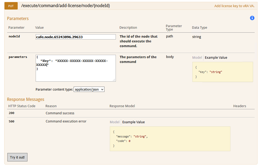
i) Click on the PUT /execute/command/add-license/node/{nodeId}
command, the following will be displayed:
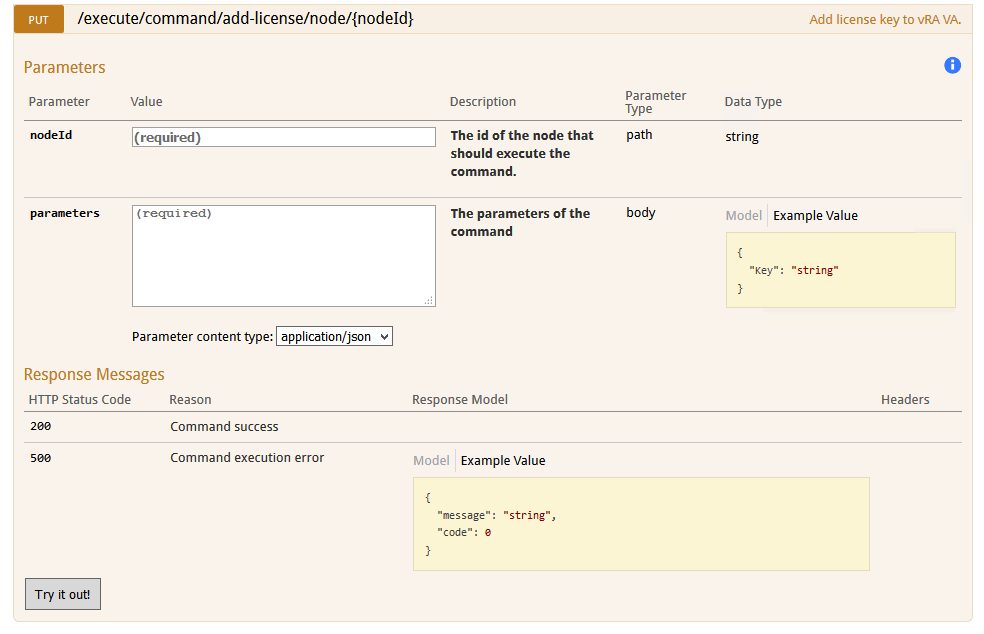
j) Enter the NodeId
captured in h) above in the nodeId
field e.g cafe.node.65243896.29633.
k) In parameters enter the following:
{
"Key": "<new license key>"
}
l) The screen should look like the following:
m) Click on the Try it out!
button.
n) If successful, the following will be displayed under the Response Body:
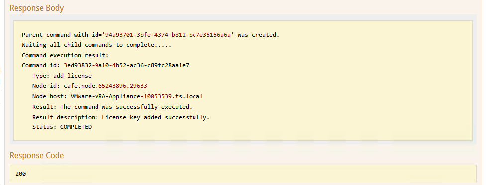
o) Result description should say “Licence key added successfully” and Status "COMPLETED".
p) That’s it, done!
8) Send an Email to additional recipients during VM provisioning in VRA 7.5
Use Case:
Send an Email with the VM details to additional teams/recipients during VM provisioning.
This can be achieved by configuring the following:
a) Create an custom property for the OS in the Blueprint called VirtualMachine.OS.Type
with the value of Windows
or Linux
depending on the blueprint type.
b) Install and configure the “Send Email” workflow provided below in vRealize Orchestrator.
c) Create the Event Broker Subscription
to trigger the “Send Email” workflow at the MachineActivated
state.
d) Add the custom property Extensibility.Lifecycle.Properties.VMPSMasterWorkflow32.MachineActivated
with the value of *
to the Blueprint in a) above.
Use the detailed steps below to achieve this:
a) Create an custom property for the operating system in the Blueprint called VirtualMachine.OS.Type
with the value of Windows
or Linux
depending on the blueprint type.
b) Add the custom property Extensibility.Lifecycle.Properties.VMPSMasterWorkflow32.MachineActivated
with the value of *
to the Blueprint in a) above.
c) Login into vRO as an administrator.
d) Select the Design
view from the drop-down.
e) Click on the folder you want to import the workflow into and right-click to display the menu below:
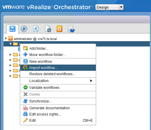
f) Select “Import Workflow” and browse to the location of the provided workflow.
g) Import the “Send Email” workflow.
h) As shown in the screenshot below:
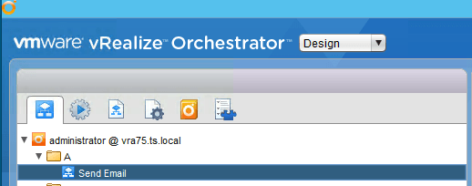
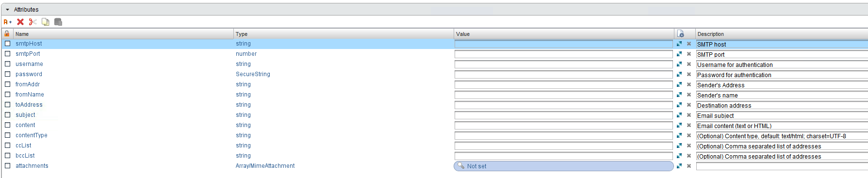
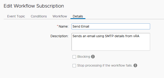
i) Edit the “Send Email” workflow and enter the correct values for Attributes
shown below:
j) Once done “Save and close” the Workflow.
k) Log into vRA as a tenant admin.
l) Go to Administration/Events/Subscription.
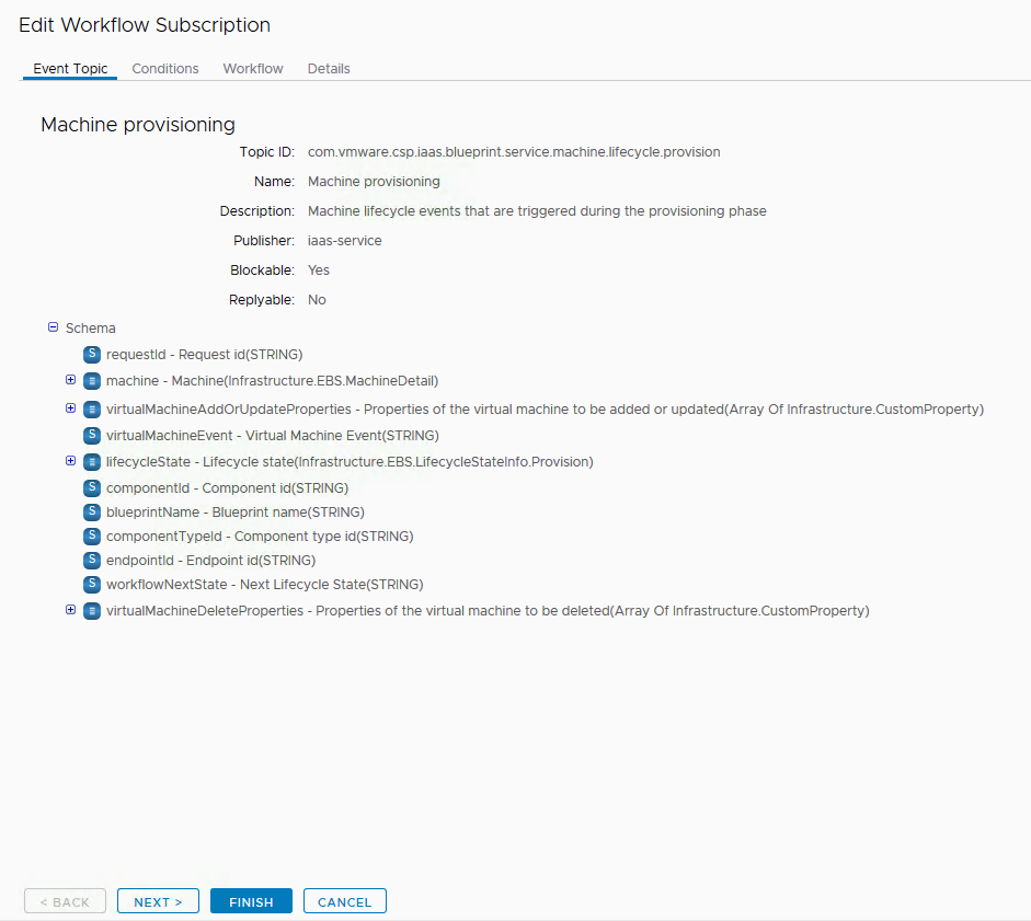
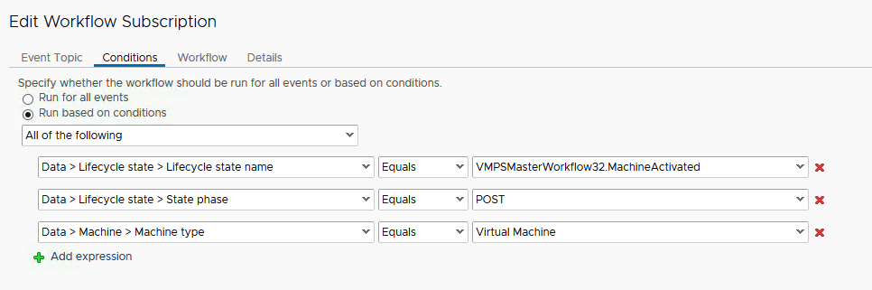
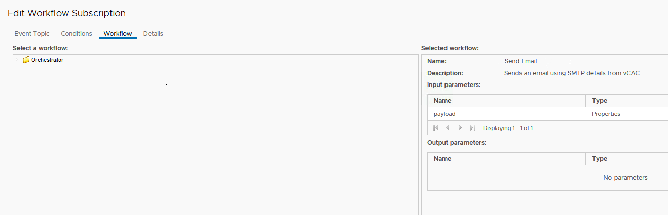
m) Create a New Subscription as shown in the example screenshots below:
n) Publish the new Subscription
created above.
o) That’s it, Done!
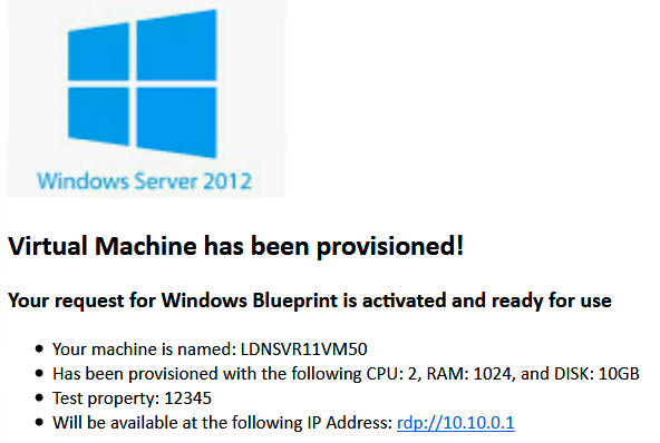
p) Provision the Blueprint on which the custom property VirtualMachine.OS.Type
was added in Step a) and see if the Email is sent successfully.
q) An example email is shown below:
9) Virtual Machine Active Directory OU placement with vRealize Automation 7.5
Posted: 5th April 2019
10) Using Custom Forms in vRealize Automation 7.6
Posted: 26th June 2019
11) vRA 7.6 Migration Checklist from vRA 7.4 onwards
Posted: 2nd Oct 2019
Enjoy !
vRA 7.6 Migration Checklist from 7.4 onwards
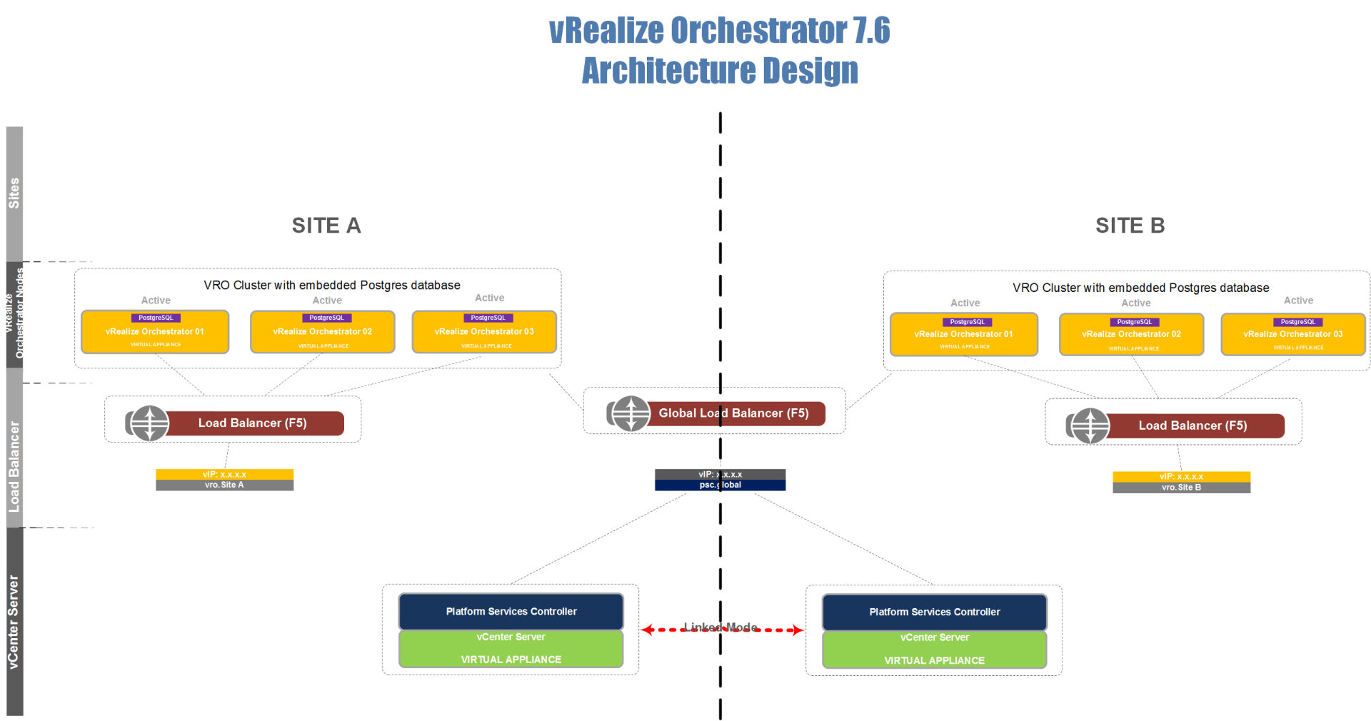
12) Dual Site vRealize Orchestrator 7.6 Architecture Design with vCenter Embedded PSCs in Linked Mode
Posted: 17th October 2019
Recently I did a project where resiliency and redundancy both local and geographic were key requirements that had to be adhered to in a vRealize Orchestrator design.
The customer had an in-house written web portal that would connect to either site to execute workflows, actions, etc.
I therefore created and implemented the following vRealize Orchestrator 7.6 design:
Design Principles:
a) Geographical Redundancy of vRealize Orchestrator:
Use 2 x 3 node vRO Clusters. One in Site A and the other in Site B.
b) Node Redundancy in cluster – In case of node failure workflows should continue to run:
vRO Clusters running in Active/Active mode.
c) Redundant vSphere Authentication:
Load balancer in front of the two Embedded PSCs.
d) PostgreSQL Database Redundancy:
Database replication will run in Synchronous mode which allows automatic
failover.
Note:
• The vCenter version was 6.7.
• The vCenter 6.7 appliances were already deployed with embedded PSCs and were already setup in linked mode.
Implementation:
To implement the above design I used the following steps:
A) Created the PSCs in HA configuration, this involved the following:
a. Created a CA certificate for the PSCs which had the VIP, Node 1 and Node 2 FQDNs in the subjectAltName.
b. F5 Load balancer configured according to the KB below: https://kb.vmware.com/s/article/2147038
c. Configured the PSCs for SSL Passthrough as shown below:
i. Connected to the Site A PSC appliance and logged in with root credentials.
ii. Typed shell to access the Bash shell.
iii. Navigated to /usr/lib/vmware-sso/bin with this command:
cd /usr/lib/vmware-sso/bin
iv. Executed the command below:
python updateSSOConfig.py --lb-fqdn=PSC_HA_VIP_FQDN
Example:python updateSSOConfig.py --lb-fqdn=psc-ha-vip.domain.com
v. Repeated these steps on Site B PSC.
vi. On the Site A PSC appliance navigated to /usr/lib/vmware-sso/bin
vii. Executed the command below:
python UpdateLsEndpoint.py --lb-fqdn=PSC_HA_VIP_FQDN --user=administrative_user --password=password
Example:
python UpdateLsEndpoint.py --lb-fqdn=psc-ha-vip.domain.com --user=administrator@vsphere.local --password=VMware123
Note: This only needs to be performed on a single PSC node.
B) Created a vRO Cluster in Site A
as follows:
a. Created a Load Balancer VIP for the vRO Nodes.
b. Created a CA certificate for the vRO nodes which had the VIP, Node 1, NODE 2 and Node 3 FQDNs in the subjectAltName.
c. Deployed the 3 Appliances in vCenter in Site A.
d. Configured the NTP Servers on all three appliances in the WAMI (Port 5480).
e. Created the cluster in Control Center using the vRO VIP FQDN.
f. Connected to the WAMI i.e. port 5480 as root on the 2nd Node and in the Cluster tab, Typed the Node 1 FQDN in the Leading Cluster Node field, Typed root in the Admin User field, Typed the password and selected the Join Cluster button.
This added the 2nd Node to the cluster.
g. Connected to the WAMI i.e. port 5480 as root on the 3rd Node and in the Cluster tab, Typed the Node 1 FQDN in the Leading Cluster Node field, Typed root in the Admin User field, Typed the password and selected the Join Cluster button.
This added the 3rd Node to the cluster as well.
h. Connected to the WAMI i.e. port 5480 as root on the 1st Node and in the Cluster tab selected the Sync button to setup Synchronous PostgreSQL database replication. This would provide automatic database failover capability with one node as Master, one node at Synced replica and one node as Potential replica.i. Added the new certificate created in b. above to Control Center under Certificates.j. Changed the Authentication provider in Control Center to use vSphere authentication by entering the VIP FQDN of the PSCs and the credentials.
Note:This should have also imported the PSC certificates into Control Center under Certificates in Trusted Certificates. If both the PSC certificates are not listed, then add the missing one manually by pointing to the vCenter FQDN URL.
C) Created a vRO Cluster in Site B
using the same steps in B) above.
D) That’s it, All done !
13) vRealize Automation 7.6 Pre-requisites when installing with VMware Cloud Foundation 3.8 SDDC Manager and vRealize Suite Lifecycle Manager
Posted: 16th Nov 2019.
I recently had the opportunity to work on a project to install vRealize Automation 7.6 on VMware Cloud Foundation 3.8. Basically the deployment is initiated in VMware Cloud Foundation SDDC Manager, which then calls the vRealize Suite Lifecycle Manager APIs to deploy vRealize Automation.
Something that I learnt from this project was that the pre-requisites were very important in order to have a successful deployment. I therefore created a pre-requisites checklist which I am sharing below so that anyone trying to deploy vRA 7.6 on VCF 3.8 can do so without issues:
Task
1. Service account for vRA and permission to add VMs to the domain.
2. A Certificate for all the vRA Components.
3. vRA License Key.
4. DNS Entries for all the vRA LB VIPs, Appliances and Windows VMs.
5. IaaS SQL Server:
a) SQL Server Version 2016 or 2017.
b) Create an Empty vRA database with the following settings:
i) Set Recovery Model option to Simple.
ii) Set Compatibility Level as 100 or 120.
iii) Under Other options, change the Allow Snapshot Isolation option to true.
iv) Under Other options, change the Is Read Committed Snapshot option to true."
c) Ensure the Server is on the domain.
d) Add the service account as part of the SQL DB user Logins list with the sysadmin privilege.
e) Configure MSDTC as per https://docs.vmware.com/en/VMware-Cloud-Foundation/3.8/com.vmware.vcf.planprep.doc_38/GUID-295E5800-8E38-4522-8C10-08606DEBB8CE.html
f) Configure the Windows Firewall to allow inbound access for Microsoft SQL Server and the Microsoft Distributed Transaction Coordinator (MSDTC).
g) Ensure there are no SQL Triggers configured on the SQL Server. If they are then disable them.
6. Windows OVA Template:
a) Windows 2016 Server (64 bit)
b) 2 vCPU, 8GB Memory, 50GB Disk and Network VMXNET3.
c) Install latest JRE (Java 1.8 or later) and create a JAVA_HOME environment variable.
d) Install Microsoft .NET Framework 3.5.
e) Install Microsoft .NET Framework 4.5.2 or later.
f) Configure MSDTC as per https://docs.vmware.com/en/VMware-Cloud-Foundation/3.8/com.vmware.vcf.planprep.doc_38/GUID-295E5800-8E38-4522-8C10-08606DEBB8CE.html.
g) Set the Powershell execution policy to Unrestricted i.e. "Set-ExecutionPolicy Unrestricted".
h) Update the registry key below:
a. Use the default PowerShell and run the following command as administrator on all Windows and database server virtual machines:
Set-ItemProperty -Path "HKLM:\Software\Microsoft \Windows\CurrentVersion\Policies\System" -Name "EnableLUA" -Value "0"
b. Reboot the Windows virtual machine.
i) Verify that the TLS 1.0 and 1.1 values are not present in the IaaS windows machine registry path below:
HKLM SYSTEM\CurrentControlSet\Control\SecurityProviders\SCHANNEL\Protocols
j) Disable IPv6:
Set-ItemProperty -Path ‘HKLM:\System\CurrentControlSet\Services\TCPIP6\Parameters’ -Name 'DisabledComponents' -Value 0xf
k) Verify that the source path for Microsoft Windows Server is available offline.
a. Copy the Microsoft Windows Server source directory \sources\sxs from the Windows install media to the virtual machine folder C:\sources\sxs.
b. Update the registry string value for HKEY_LOCAL_MACHINE\SOFTWARE\Microsoft\Windows \CurrentVersion\policies\Servicing\LocalSourcePath to location of the installation files.For example, C:\sources\sxs. If the Servicing key is missing, create it. LocalSourcePath is a string value.
l) Enable secondary log-in with an automatic start-up.
m) Add the VM to the domain.
n) Add the service account to the Local Administrators group.
o) Add the service account as part of User Rights Assignment under Local Security Policies for Log on as a Service and Log on as a batch job.
p) Reboot the Windows virtual machine.
q) Log in to windows machine at least once as the service account.
r) Shut down the Microsoft Windows Server virtual machine and export as OVA template with ovftool, i.e:
ovftool --noSSLVerifyvi://'administrator@vsphere.local':'<VC_Password>'@<VC_IP_or_FQDN>/<Datacenter_Name>/vm/<VM_Name>\<IAAS_Template_Name>.ova
Observations
a) The vRA Load Balancers will be created automatically as part of the deployment process.
b) All the IaaS components are deployed in a Large Deployment profile.
c) All IaaS components must be entered in the Wizard i.e. 3 vRA Appliances, 2 Web Servers, 2 Manager Service Servers, 2 DEM Worker Servers and 2 Proxy Agent Servers.
d) 6 Instances of the DEM Workers are installed. i.e. 3 per DEM Worker server.
e) The vSphere Proxy Agents are NOT
installed. They have to be installed manually as a post installation step.
f) Both the Manager Services are running and the vRA Appliance monitors which one is Active and which one is Passive.
g) All the vRA components are added to Log Insight.
h) The vRA PostgreSQL database is set to Synchronous replication.
I) vRealize Automation environment added to vRealize Suite Lifecycle Manager.
j) When an Active Directory is configured then the 2nd and 3rd connectors will need to be added manually post deployment to the Identity provider and the idP Hostname set to the VIP Address of the Appliances.
14) vRealize Automation 7.6 Pre-requisites when installing with vRealize Suite Lifecycle Manager 2.1
Posted: 29th Nov 2019.
One of my recent projects was to install vRealize Automation 7.6 in a Large deployment profile using vRealize Suite Lifecycle Manager 2.1. Once again I found that the pre-requisites were very important for a successful deployment.
In this deployment the Windows IaaS Servers had been pre-built and therefore had to make sure that all the pre-requisites had been installed before initiating the vRA deployment with vRSLCM.
I have created a pre-requisites checklist which I am sharing below that enabled a successful deployment:
Task
1. Configure the vRealize Automation load balancers for Virtual Appliances, IaaS Web and IaaS Manager.
2. Disable the second/third member of each pool in the vRealize Automation load balancers. These members can be re- enabled after installation is complete.
3. Add all Windows IaaS machines to the domain.
4. The Windows SQL database server and Windows IaaS machines meet all vRealize Automation version and resource requirements.
5. Add the domain vRA service account as part of User Rights Assignment under Local Security Policies for Log on as a Service
and Log on as a batch job
on all Windows IaaS machines.
6. Join the IaaS SQL server to the domain.
7. Add the domain vRA service account as part of the SQL server user Logins list with the sysadmin privilege.
8. Install latest JRE (Java 1.8 or later) and create a JAVA_HOME environment variable on all Windows IaaS machines.
9. Install Microsoft .NET Framework 3.5 on all Windows IaaS machines.
10. Install Microsoft .NET Framework 4.5.2 or later on all Windows IaaS machines.
11. Install Microsoft Internet Information Services on the Windows IaaS Web Servers and IaaS Manager Service Servers and configured with the relevant roles and features.
12. Enable MSDTC on both the Windows IaaS Servers and the SQL Database Server. See VMware Knowledge Base article 2038943.
12. Set User Access Control settings to Never Notify
on all Windows IaaS and SQL database server virtual machines.
13. On all of the windows IaaS machines used in vRealize Automation deployment, log in to windows machine at least once as the domain vRA service account.
14. Ensure that the Windows IaaS machines do not have any vRealize Automation components already installed.
15. Update the registry key below on both Windows IaaS and SQL database server virtual machines:
a. Use the default PowerShell and run the following command as administrator on all
Windows IaaS and database server virtual machines:
Set-ItemProperty -Path "HKLM:\Software\Microsoft
\Windows\CurrentVersion\Policies\System" -Name "EnableLUA" -Value "0"
b. Reboot the Windows IaaS virtual machine.
16. Verify that the TLS 1.0 values are not present in the IaaS windows machines registry path below:
HKLM SYSTEM\CurrentControlSet\Control\SecurityProviders\SCHANNEL\Protocols.
17. Verify that TLS 1.1 and 1.2 are enabled as per https://docs.vmware.com/en/vRealize-Automation/7.6/com.vmware.vra.install.upgrade.doc/GUID-CFCCC0C1-A8EB-4C9F-B68D-14249D292496.html.
18. Take a snapshot of the IaaS SQL database machine and all Windows IaaS machines after configuration and before triggering the deployment in vRealize Suite Lifecycle Manager.
Observations
a) 2 Instances of the DEM Workers are installed i.e. 1 per DEM Worker server.
b) 2 vSphere Proxy Agents are installed i.e. 1 per Proxy server.
c) Only the Primary Manager Service is running and the Secondary one is set to manual and stopped.
d) The vRA PostgreSQL database is set to Asynchronous replication. If 3 appliances are used then this will need to be set to Synchronous replication post deployment.
e) vRealize Automation environment is added to vRealize Suite Lifecycle Manager.
f) When an Active Directory is configured then the 2nd and 3rd connectors will need to be added manually post deployment to the Identity provider and the idP Hostname set to the VIP Address of the Appliances.